Objectives:
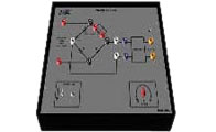
The inverter circuit consist of a transformer with a center tapped primary connected to two SCR's driven by two pulse
transformers connected to UJT's. Independent L,C,R loads are provided for loading the inverter to study the resulting wave
forms.
Specifications:
SCR T 2162/106D - 1 NO
Power diodes RTF - 20 - 1 No
Capacitors 4MF,0.047/1 (40V) - 2 Nos
Inductive load 1.75H - 2 Nos
Resistive load 4.7K,10W - 4 Nos
Power transformer 230V-PRIMARY 18 - 0- 18V SEC @ 1A - 1 No .
Patch chords 2mm - 2mm - 6 NOS LONG - 4 SMALL - 2.
1:34 attenuator for oscilloscope - 1 No
External power supply required to conduct the experiment - 0-30V@1A - 1 No .
Diodes - IN4007, PFR 852 - 2 Nos.
Inductors 3.5H,250 MH - 2 Nos
Resistors 220W,5W,1K.1/4W/3,0.1E,5W/2 - 5 Nos.
Capacitive load 0.01MF (400V) - 2 Nos .
Potentiometer 5K,1W - 1 No.
IC 555 timer - 1 No .
Zener diode - 10V/1W - 1 No
User manual - 1 No
 Novel Instruments